
Short answer: Pick the inductance from the ripple you accept, then check three limits in order: saturation current (Isat) against the peak current, heating current (Irms, called Idc by MAZO) against the RMS current, and DCR and part temperature against your loss and thermal budget. Then choose shielding, body size and, for automotive work, AEC-Q200. The full guide with all tables is at [Power inductor selection guide](/buying-guides/power-inductor-selection-guide).
Step 1: Follow the selection order
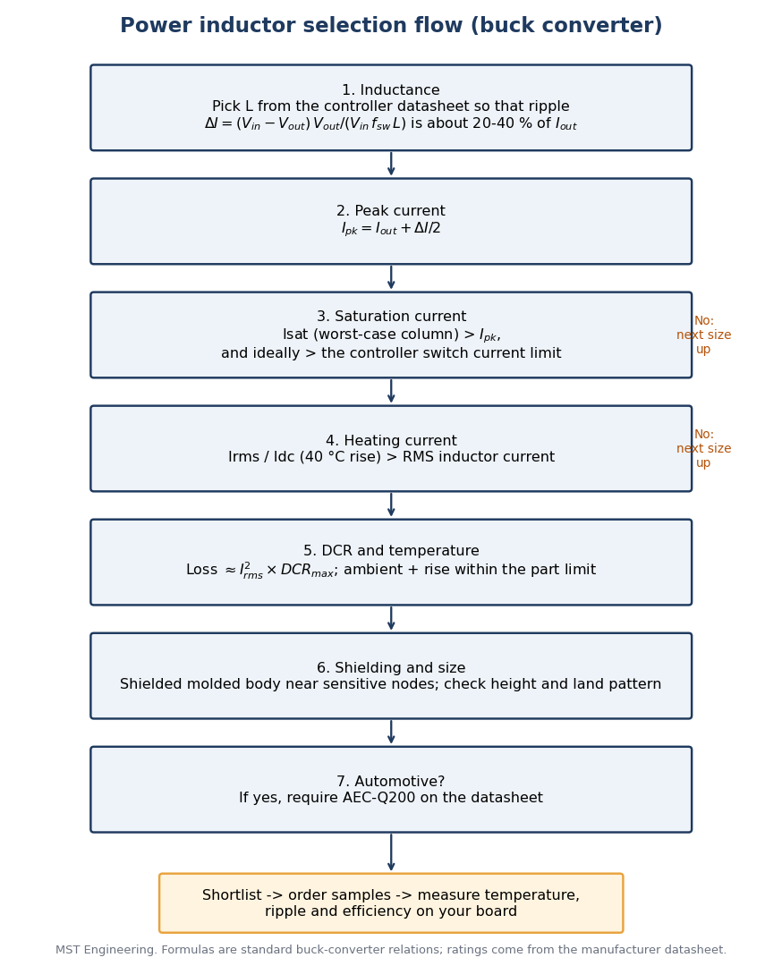
Selection flow drawn by MST Engineering. Formulas are standard buck-converter relations.
1. Inductance: in a buck converter, ripple ΔI = (Vin − Vout) × Vout / (Vin × fsw × L). Start from the range in your controller datasheet.
2. Peak current: Ipk = Iout + ΔI/2.
3. Isat above Ipk, and ideally above the controller switch current limit, which the inductor sees at start-up or during a short.
4. Heating current above the RMS inductor current.
5. Copper loss ≈ Irms² × DCR max; ambient plus rise must stay within the part limit (125 °C for MAZO).
Step 2: Isat and Irms are different limits
| Rating | MAZO definition | Compare with |
|---|---|---|
| Isat | DC current that causes L0 to drop approximately 30 % | Peak current and controller current limit |
| Idc (heating) | DC current for an approximate 40 °C rise, 25 °C ambient | RMS inductor current |
| Part temperature | Ambient + rise must not exceed 125 °C | Worst-case ambient + measured rise |
In the MAZO VCMA tables the MAX current column is the lower figure; use it as the conservative design value.
Step 3: Same 2.2 µH, six bodies
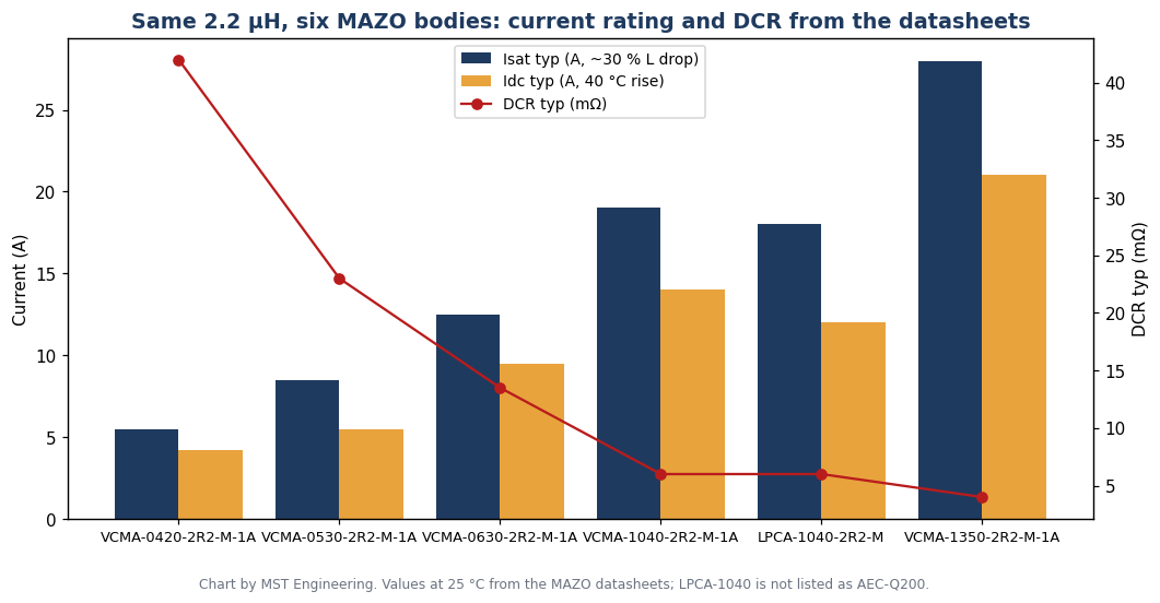
Chart by MST Engineering from the MAZO datasheets.
| Part number | Max size (mm) | DCR typ / max (mΩ) | Idc typ / max (A) | Isat typ / max (A) | Rated V | AEC-Q200 |
|---|---|---|---|---|---|---|
| [VCMA-0420-2R2-M-1A](/store/mazo-power-inductors/VCMA-0420-2R2-M-1A) | 4.75 × 4.45 × 2.0 | 42.0 / 50.0 | 4.2 / 4.0 | 5.5 / 5.0 | 40 | Yes |
| [VCMA-0530-2R2-M-1A](/store/mazo-power-inductors/VCMA-0530-2R2-M-1A) | 5.7 × 5.4 × 3.0 | 23.0 / 26.0 | 5.5 / 5.0 | 8.5 / 8.0 | 50 | Yes |
| [VCMA-0630-2R2-M-1A](/store/mazo-power-inductors/VCMA-0630-2R2-M-1A) | 7.3 × 6.8 × 3.0 | 13.5 / 15.0 | 9.5 / 9.0 | 12.5 / 12.0 | 75 | Yes |
| [VCMA-1040-2R2-M-1A](/store/mazo-power-inductors/VCMA-1040-2R2-M-1A) | 11.5 × 10.3 × 4.0 | 6.0 / 7.0 | 14.0 / 12.0 | 19.0 / 18.0 | 75 | Yes |
| LPCA-1040-2R2-M | 11.5 × 10.3 × 4.0 | 6.0 / 7.0 | 12.0 (typ) | 18.0 (typ) | Not stated | Not listed |
| [VCMA-1350-2R2-M-1A](/store/mazo-power-inductors/VCMA-1350-2R2-M-1A) | 13.8 × 12.9 × 5.0 | 4.0 / 4.6 | 21.0 / 19.0 | 28.0 / 26.0 | 75 | Yes |
Inductance ±20 % at 1 MHz, 1.0 V, values at 25 °C.
Step 4: Worked example, 12 V to 3.3 V at 3 A, 1 MHz
1. ΔI = (12 − 3.3) × 3.3 / (12 × 1 MHz × 2.2 µH) ≈ 1.09 A; Ipk ≈ 3.54 A; Irms ≈ 3.02 A.
2. VCMA-0420-2R2-M-1A: Isat 5.0 A and Idc 4.0 A (MAX columns) pass; DCR loss ≈ 0.46 W.
3. VCMA-0530-2R2-M-1A: Isat 8.0 A and Idc 5.0 A leave more margin above a controller limit; DCR loss ≈ 0.24 W.
4. Decide on the controller current limit, board temperature and height (2.0 vs 3.0 mm), then measure on the board.
Step 5: Shielding, size and footprint
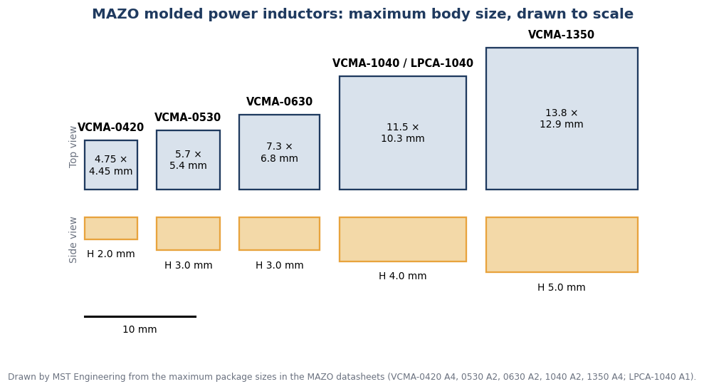
Maximum body sizes drawn to scale by MST Engineering from the MAZO datasheets.
All series here are molded bodies that the datasheets describe as magnetically shielded, low EMI. Copy the land pattern from the datasheet of the exact series:
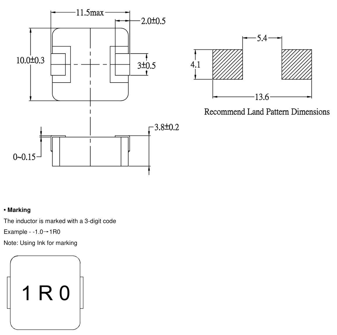
Dimension drawing from the MAZO VCMA-1040 datasheet (rev A2), reproduced by MST.
Step 6: AEC-Q200
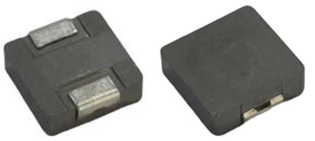
Representative series photo of MAZO VCMA-0420.
Original OEM documents (links only)
1. Kun Shan MAZO Tech Co., Ltd., VCMA and LPCA datasheets: linked from each product page, for example [VCMA-1040-2R2-M-1A](/store/mazo-power-inductors/VCMA-1040-2R2-M-1A).
2. Automotive Electronics Council, AEC-Q200. http://www.aecouncil.com/AECDocuments.html
Ask an engineer
Send your Vin, Vout, load current, switching frequency and height limit through [Ask an engineer](/rfq?entry_source=ask_engineer&search_term=power+inductor+selection&quantity=1&community_path=%2Fcommunity%2Fc%2Fpower-inductors). MST replies with MAZO candidates, samples, price and lead time. Browse [MAZO power inductors](/store/mazo-power-inductors) or try the [MAZO inductor selector](/tools/mazo-inductor-selector). For parts outside this list, use a [sourcing RFQ](/services/sourcing-rfq?sourcing_mode=supplier_match) or [post a part request](/community/new?kind=part_request).
Parts