
Short answer: A die fits an open-cavity QFN when four checks pass. The die X and Y must be no larger than the nominal die-attach area. The die thickness plus attach material and wire-loop height must stay below the cavity depth. The die pad count must be no more than the package connection count. The package pitch must match your socket or board. For example, a 3.0 × 3.0 mm die fits an ALNP-32-5-5 (3.30 mm die-attach area, 0.15 mm margin per side) but not an ALNP-16-3-5 (1.36 mm).
Package data below comes from the dimension summaries for the ALN plastic air-cavity QFN packages listed on MST Store. MST distributes these packages and is not the manufacturer. Always confirm against the manufacturer drawing for the exact part number.
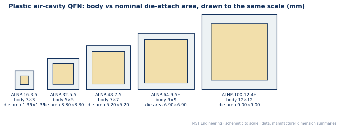
Diagram drawn by MST Engineering to scale from the manufacturer dimension summaries.
Step 1: Check die X and Y against the die-attach area
| Package | Body | Connections | Pitch | Cavity depth | Nominal die-attach area |
|---|---|---|---|---|---|
| [ALNP-16-3-5](/store/empty-ic-packages/ALNP-16-3-5) | 3.00 × 3.00 mm | 16 | 0.5 mm | 0.65 mm | 1.36 × 1.36 mm |
| ALNP-24-4-5 | 4.00 × 4.00 mm | 24 | 0.5 mm | 0.65 mm | 2.30 × 2.30 mm |
| [ALNP-32-5-5](/store/empty-ic-packages/ALNP-32-5-5) | 5.00 × 5.00 mm | 32 | 0.5 mm | 0.65 mm | 3.30 × 3.30 mm |
| ALNP-36-6-5 | 6.00 × 6.00 mm | 36 | 0.5 mm | 0.65 mm | 4.24 × 4.24 mm |
| [ALNP-48-7-5](/store/empty-ic-packages/ALNP-48-7-5) | 7.00 × 7.00 mm | 48 | 0.5 mm | 0.65 mm | 5.20 × 5.20 mm |
| ALNP-56-8-5H | 8.00 × 8.00 mm | 56 | 0.5 mm | 1.25 mm | 6.04 × 6.04 mm |
| ALNP-64-9-5H | 9.00 × 9.00 mm | 64 | 0.5 mm | 1.25 mm | 6.90 × 6.90 mm |
| ALNP-72-10-5 | 10.00 × 10.00 mm | 72 | 0.5 mm | 0.65 mm | 7.80 × 7.80 mm |
| ALNP-100-12-4H | 12.00 × 12.00 mm | 100 | 0.4 mm | 1.25 mm | 9.00 × 9.00 mm |
Work out the margin per side as (die-attach area − die size) ÷ 2. A negative margin means the die does not fit. A small positive margin leaves little room for die placement tolerance and attach fillet, so discuss it with your assembly house.
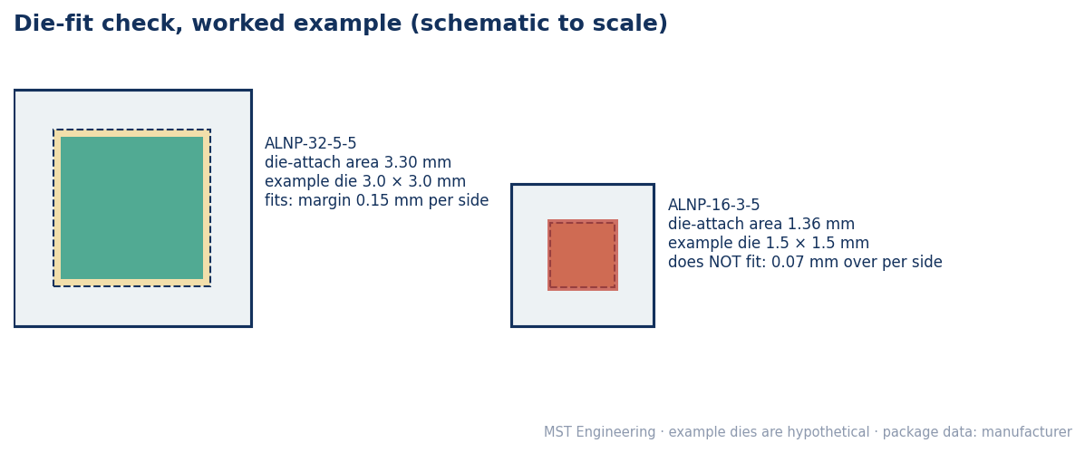
Worked example by MST Engineering. The example dies are hypothetical; the package data comes from the manufacturer.
Step 2: Check the height stack against the cavity depth
The same body often comes in more than one cavity depth. For example, the ALNP-32-5-5 has a 0.65 mm cavity and the ALNP-32-5-5H has 1.25 mm. The ALNP-40-6-5F is a shallow 0.25 mm version.
1. Add the die thickness, the die-attach thickness and the wire-loop height above the die.
2. Compare the total with the cavity depth. Leave clearance for the lid so it does not touch the wires.
3. If the stack is too tall, choose an H (1.25 mm) variant of the same body, or thin the die.
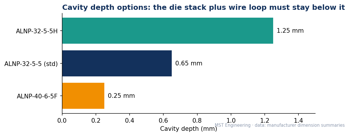
Chart by MST Engineering from the manufacturer dimension summaries.
Step 3: Check pad count, pitch and bond layout
1. The die pad count must be no more than the package connection count. Spare leads can stay unconnected.
2. Check bond-wire length and angle from each die pad to its bond finger. Very long or steep wires from a small die in a large cavity add risk.
3. Choose the pitch your socket or board uses. Packages with the same body come in different pitches (ALNP-28-4-4 at 0.4 mm and ALNP-24-4-5 at 0.5 mm are both 4 × 4 mm).
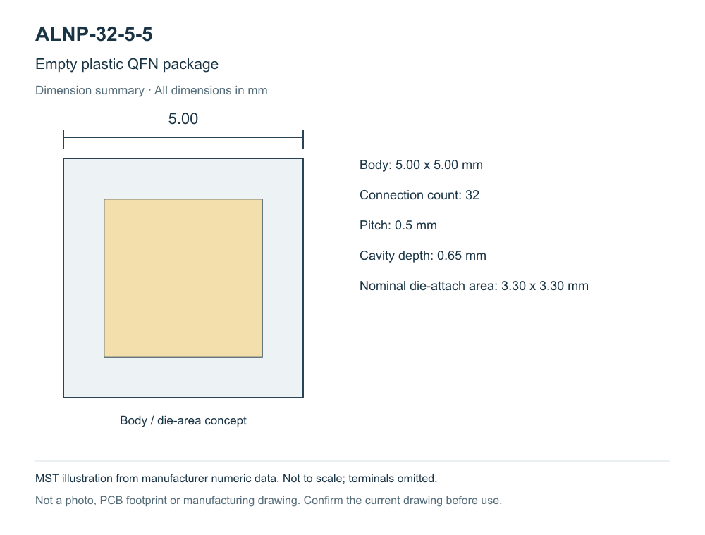
MST schematic drawn from the manufacturer numeric specifications. It is not to scale and omits terminals.
Step 4: Plan the lid and the test socket
1. Plastic air-cavity QFNs take a black alumina lid of the same body size with pre-applied B-stage epoxy (PCLID0303 to PCLID1010; for example, [PCLID0505](/store/ic-package-lids/PCLID0505) for a 5 × 5 mm package).
2. The ALNP packages follow JEDEC MO-220 outlines, so a QFN socket for the same body, lead count and pitch should fit. See the [QFN socket selection tutorial](/community/c/test-sockets).
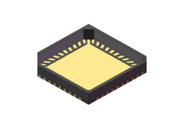
Manufacturer rendering (Shanghai Xintaowei 2026 product brochure), not a photograph.
RFQ checklist
1. Die X × Y and thickness, pad count and the bond-pad layout.
2. Wire type and the expected loop height.
3. Required pitch, or the socket you will use.
4. Lid and seal needs (epoxy or hermetic) and quantity.
Original OEM documents (links only)
1. ALN (Shanghai), open-cavity package manufacturer. https://www.alnchina.com.cn/
2. JEDEC, package outline standards (MO-220 QFN). https://www.jedec.org/
Ask an engineer
Send your die size, thickness and pad count through [Ask an engineer](/rfq?entry_source=ask_engineer&search_term=open-cavity+die+fit&quantity=1&community_path=%2Fcommunity%2Fc%2Fic-packages-lids). MST checks the fit with the manufacturer and replies with price and lead time. Browse [empty IC packages](/store/empty-ic-packages), or post a [find-part request](/community/new?kind=part_request&mpn=ALNP-32-5-5). For parts outside this list, use a [sourcing RFQ](/services/sourcing-rfq?sourcing_mode=supplier_match).
Parts
Catalog parts in this guide
- ALNP-16-3-5 empty plastic qfn package, 3.00 x 3.00 mm
- ALNP-32-5-5 empty plastic qfn package, 5.00 x 5.00 mm
- ALNP-32-5-5H empty plastic qfn package, 5.00 x 5.00 mm
- ALNP-48-7-5 empty QFN48 LCP package, 7 x 7 mm
- ALNP-40-6-5F empty plastic qfn package, 6.00 x 6.00 mm
- ALNP-64-9-5H empty plastic qfn package, 9.00 x 9.00 mm