
How to choose a power inductor: inductance, Isat, Irms, DCR, size and AEC-Q200
A power inductor in a buck or boost converter is chosen in a fixed order: inductance from the ripple you accept, saturation current from the peak current, heating current from the RMS current, then DCR, shielding, body size and qualification. This guide walks through each step with a worked example.
The comparison tables use the molded power inductors made by Kun Shan MAZO Tech Co., Ltd. that MST stocks, with every value copied from the MAZO datasheet listed under Sources. MST is a distributor of MAZO parts, not the manufacturer.
Step 1: Pick the inductance from the ripple current
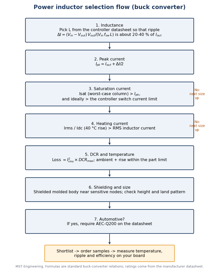
Start from the inductance range in your controller datasheet. In a buck converter in continuous conduction the peak-to-peak ripple is ΔI = (Vin − Vout) × Vout / (Vin × fsw × L). Many controller datasheets suggest a ripple of roughly 20 to 40 % of the full load current; follow your controller vendor where it gives a figure.
A larger inductance lowers ripple and output-voltage ripple, but for the same body it means more turns, a higher DCR and a lower saturation current. A smaller inductance does the opposite and raises the peak current.
Step 2: Isat vs Irms: two different current limits
Saturation current (Isat) is a magnetic limit: the DC current at which the inductance has dropped by a stated amount. MAZO defines it as the current that causes L0 to drop approximately 30 %. Compare it with the peak inductor current Ipk = Iout + ΔI/2, and preferably with the controller switch current limit, because at start-up or during a short the controller drives the inductor up to that limit.
Heating current (Irms, called Idc in MAZO datasheets) is a thermal limit: the DC current that causes an approximate 40 °C temperature rise from 25 °C ambient. Compare it with the RMS inductor current, which for a buck is close to the load current. A part can pass one limit and fail the other, so check both.
MAZO VCMA tables print a TYP and a MAX column for Idc and Isat, and the MAX column is the lower figure. Use the lower figure as the conservative design value and confirm with MAZO through MST if your margin is small.
| Rating | MAZO definition | Compare with |
|---|---|---|
| Isat | DC current that causes L0 to drop approximately 30 % | Peak inductor current, and the controller current limit |
| Idc (heating current) | DC current that causes an approximate ΔT of 40 °C, 25 °C ambient | RMS inductor current at the worst ambient |
| Part temperature | Ambient plus temperature rise must not exceed 125 °C | Worst-case ambient plus measured rise |
Step 3: Same 2.2 µH, six bodies: datasheet comparison
At a fixed inductance, a larger body buys saturation current, heating current and a lower DCR. The table lists the 2.2 µH part of each MAZO series that MST stocks.
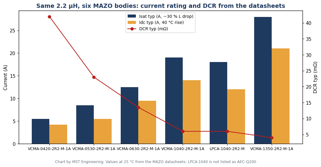
| Part number | Max size L × W × H (mm) | DCR typ / max (mΩ) | Idc typ / max (A) | Isat typ / max (A) | Rated voltage (V) | AEC-Q200 |
|---|---|---|---|---|---|---|
| VCMA-0420-2R2-M-1A | 4.75 × 4.45 × 2.0 | 42.0 / 50.0 | 4.2 / 4.0 | 5.5 / 5.0 | 40 | Yes |
| VCMA-0530-2R2-M-1A | 5.7 × 5.4 × 3.0 | 23.0 / 26.0 | 5.5 / 5.0 | 8.5 / 8.0 | 50 | Yes |
| VCMA-0630-2R2-M-1A | 7.3 × 6.8 × 3.0 | 13.5 / 15.0 | 9.5 / 9.0 | 12.5 / 12.0 | 75 | Yes |
| VCMA-1040-2R2-M-1A | 11.5 × 10.3 × 4.0 | 6.0 / 7.0 | 14.0 / 12.0 | 19.0 / 18.0 | 75 | Yes |
| LPCA-1040-2R2-M | 11.5 × 10.3 × 4.0 | 6.0 / 7.0 | 12.0 (typ) | 18.0 (typ) | Not stated | Not listed |
| VCMA-1350-2R2-M-1A | 13.8 × 12.9 × 5.0 | 4.0 / 4.6 | 21.0 / 19.0 | 28.0 / 26.0 | 75 | Yes |
Inductance ±20 % at 1 MHz, 1.0 V. The LPCA-1040 datasheet gives typical currents only and lists computing applications (VRM, SSD, notebook regulators) rather than AEC-Q200.
Step 4: Worked example: 12 V to 3.3 V at 3 A, 1 MHz
- Ripple with 2.2 µH: ΔI = (12 − 3.3) × 3.3 / (12 × 1 MHz × 2.2 µH) ≈ 1.09 A, about 36 % of 3 A.
- Peak current: Ipk = 3 + 1.09 / 2 ≈ 3.54 A. RMS current ≈ 3.02 A.
- VCMA-0420-2R2-M-1A: Isat 5.0 A (MAX column) > 3.54 A and Idc 4.0 A > 3.02 A, so it passes on paper. DCR loss ≈ 3.02² × 50 mΩ ≈ 0.46 W.
- VCMA-0530-2R2-M-1A: Isat 8.0 A and Idc 5.0 A leave more margin, for example above a controller current limit between 5 and 8 A, and DCR loss falls to ≈ 0.24 W at 26 mΩ.
- Choose between them on the controller current limit, the board temperature and the height you can allow (2.0 mm vs 3.0 mm), then verify on the board.
Step 5: DCR, losses and part temperature
Copper loss is roughly Irms² × DCR; use the maximum DCR for worst case. Core loss depends on ripple and frequency and is not in the summary tables, so measure temperature rise on the real board.
The MAZO datasheets limit the part temperature (ambient plus self-heating) to 125 °C. If your ambient is 85 °C, the inductor may rise only 40 °C, which is the same rise used to define Idc, so a hot board needs more current margin.
Step 6: Shielding, size and footprint
Every MAZO series in this guide is a molded body described in its datasheet as magnetically shielded, low EMI. A shielded part keeps the stray field away from feedback traces, sensitive analog nodes and nearby magnetics; an unshielded drum core is cheaper but radiates more and needs more layout care.
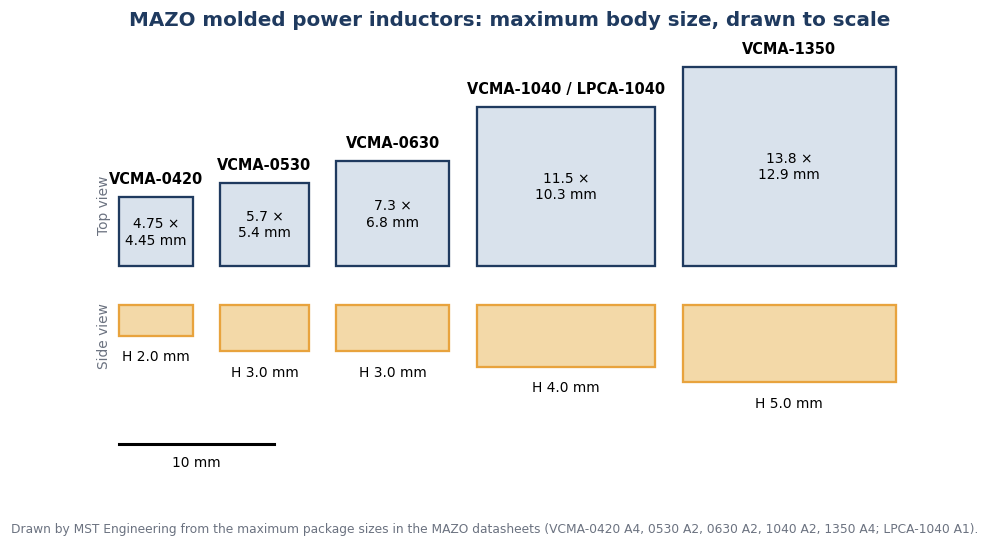
Size is the main trade-off. Compare the maximum body sizes below with your height limit and copy the land pattern from the datasheet of the exact series, because bodies with the same inductance differ in footprint.
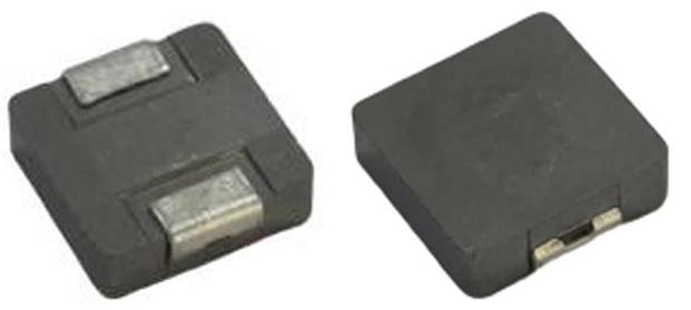
Supplier dimension drawing and product photo
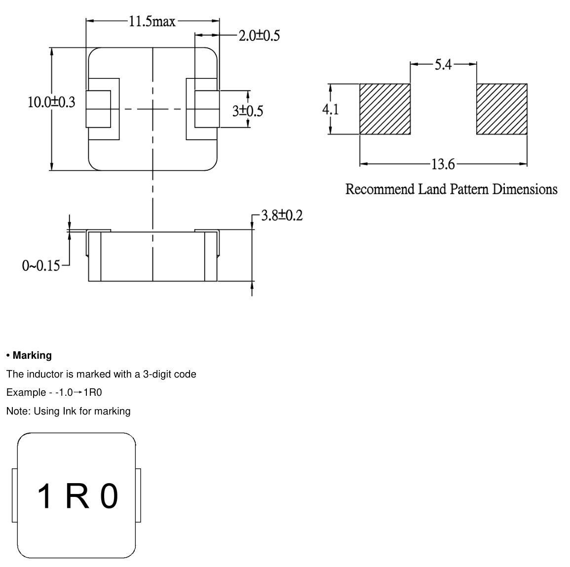
The VCMA-1040 outline below is reproduced from the MAZO datasheet; the photo is a representative MAZO series photo. Check the drawing of the exact series you order.
Step 7: AEC-Q200 for automotive designs
AEC-Q200 is the Automotive Electronics Council stress-test qualification for passive components. The VCMA-0420, 0530, 0630, 1040 and 1350 datasheets each state AEC-Q200 qualified, with an operating range of −55 °C to +125 °C including self-heating. The LPCA-1040 datasheet does not list AEC-Q200, so use the VCMA-1040 in the same 11.5 × 10.3 × 4.0 mm body for automotive work.
Qualification alone is not program approval: confirm the grade, PPAP and change-notification requirements of your customer with the manufacturer.
Frequently asked questions
Should I size the inductor to Isat or to Irms?
To both. Isat must exceed the peak current (and ideally the controller current limit) so the inductance does not collapse; the heating current (Irms or Idc) must exceed the RMS current so the part stays within its temperature limit.
Which MAX or TYP value should I use from a MAZO table?
In the MAZO VCMA tables the MAX current column is the lower figure. Use it as the conservative design value, and ask MST to confirm with MAZO if your margin is small.
Is a bigger inductor always better?
For the same inductance a bigger MAZO body has a higher Isat, higher Idc and lower DCR (for 2.2 µH, from 5.5 A Isat in VCMA-0420 to 28.0 A in VCMA-1350), but it costs board area and height. Choose the smallest body that passes the current, temperature and loss checks.
Are MAZO VCMA inductors AEC-Q200 qualified?
The VCMA-0420, 0530, 0630, 1040 and 1350 datasheets state AEC-Q200 qualification. The LPCA-1040 datasheet does not.
Can I replace a Coilcraft XAL or Bourns SRP part with MAZO?
Often there is a same-value candidate, but the test conditions, ratings and footprints differ. See the XAL4020 cross-reference guide and verify the candidate on your board.
Is MST the manufacturer?
No. These inductors are made by Kun Shan MAZO Tech Co., Ltd. MST is a distributor and replies with samples, pricing and lead time.
Ask an engineer
Send your input and output voltage, load current, switching frequency, height limit and quantity. MST, as distributor, replies with MAZO candidates, sample availability and pricing.
Ask an engineerRelated pages
Sources
- MAZO VCMA-0420 datasheet, revision A4 (2025-11-26)
- MAZO VCMA-0530 datasheet, revision A2 (2025-11-26)
- MAZO VCMA-0630 datasheet, revision A2 (2025-11-26)
- MAZO VCMA-1040 datasheet, revision A2 (2025-11-26)
- MAZO VCMA-1350 datasheet, revision A4 (2025-11-26)
- MAZO LPCA-1040 datasheet, revision A1 (2025-03-03)
- Automotive Electronics Council, AEC-Q200 documents
Values are taken from the manufacturer documents above, checked 2026-10-25. Specifications can change; confirm against the current datasheet before ordering. MST is a distributor; products are made by the manufacturers named.