
How to choose an open-cavity IC package and matching lid
An open-cavity (air-cavity) package is a finished package body with an empty cavity: you attach your own die, wire-bond it to the bond fingers and close the cavity with a lid. It is the quickest way to put MPW dies, sensors and engineering samples into a standard footprint that fits an existing socket or PCB.
This tutorial walks through the decisions in the order an assembly engineer makes them: die size, I/O count, pitch, bond fingers, plating, then the lid and how it is sealed. Every dimension below is taken from the manufacturer catalogue for parts listed on MST Store.
Step 1: Size the cavity from the die
Start from the die outline, not the package. The die must fit the die-attach area with room left for die-attach fillet and for the bond wires to leave the die edge. For the plastic air-cavity QFN family the catalogue gives a square die-attach area for each body size; the standard cavity depth is 0.65 mm, so check that the die thickness plus die-attach bond line plus wire loop height stays below the cavity depth and the lid.
If the die is close to the limit, move up one body size: the bond fingers move outward with the body, which also keeps wires shorter relative to the die.
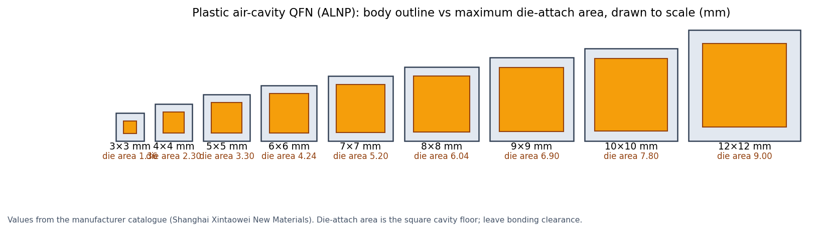
| Body size | Max. die-attach area | Example part numbers on MST Store |
|---|---|---|
| 3 × 3 mm | 1.36 × 1.36 mm | ALNP-8-3-6.5, ALNP-12-3-5, ALNP-16-3-5 |
| 4 × 4 mm | 2.30 × 2.30 mm | ALNP-12-4-6.5, ALNP-16-4-6.5, ALNP-20-4-5, ALNP-24-4-5, ALNP-28-4-4 |
| 5 × 5 mm | 3.30 × 3.30 mm | ALNP-28-5-5, ALNP-32-5-5, ALNP-32-5-5H, ALNP-40-5-4 |
| 6 × 6 mm | 4.24 × 4.24 mm | ALNP-36-6-5, ALNP-40-6-5H, ALNP-40-6-5F |
| 7 × 7 mm | 5.20 × 5.20 mm | ALNP-24-7-10, ALNP-44-7-5, ALNP-48-7-5, ALNP-48-7-5H |
| 8 × 8 mm | 6.04 × 6.04 mm | ALNP-32-8-8, ALNP-56-8-5H |
| 9 × 9 mm | 6.90 × 6.90 mm | ALNP-44-9-6.5, ALNP-64-9-5H |
| 10 × 10 mm | 7.80 × 7.80 mm | ALNP-72-10-5, ALNP-88-10-4, ALNP-96-10-4 |
| 12 × 12 mm | 9.00 × 9.00 mm | ALNP-100-12-4H |
Part numbers read ALNP-<lead count>-<body mm>-<pitch>: the last field is the lead pitch in tenths of a millimetre (5 = 0.5 mm, 4 = 0.4 mm, 6.5 = 0.65 mm, 8 = 0.8 mm, 10 = 1.0 mm). Suffix letters mark variants of the same outline, for example ALNP-48-7-5H is 1.45 mm thick against 0.85 mm for ALNP-48-7-5; check the drawing.
Step 2: Choose the package type from the I/O count
Peripheral packages (QFN, QFP) route every signal to the outer edge, so the I/O count is limited by the perimeter and the pitch. Area-array packages (BGA, LGA) use the whole underside and suit higher I/O counts in a smaller footprint, at the cost of a board that can route an array.
- Up to about 100 I/O: plastic air-cavity QFN (8 to 100 leads listed) or HTCC ceramic QFN when hermeticity matters.
- Around 144 I/O with leads you can probe: ceramic quad flat pack, for example CQFP144-01 (19 × 19 mm) or ALNC-144-20-5 (20 × 20 mm).
- 256 to 512 I/O: cavity BGA, for example BGA1313-256BALLS (13 × 13 mm) or BGA2020-512BALLS (20 × 20 mm).
- LGA (land grid array) is the same area-array idea without solder balls, used mainly with sockets. No open-cavity LGA part is listed on MST Store at present; ask an engineer if your test plan needs one.
Size comparison: open-cavity packages listed on MST Store
| Part number | Type | Body | I/O | Pitch | Die size / die-attach area |
|---|---|---|---|---|---|
| ALNP-16-3-5 | Plastic air-cavity QFN (LCP) | 3 × 3 mm | 16 | 0.5 mm | 1.36 × 1.36 mm |
| ALNP-32-5-5 | Plastic air-cavity QFN (LCP) | 5 × 5 mm | 32 | 0.5 mm | 3.30 × 3.30 mm |
| ALNP-48-7-5 | Plastic air-cavity QFN (LCP), 0.85 mm thick | 7 × 7 mm | 48 | 0.5 mm | 5.20 × 5.20 mm |
| ALNC-48-7-5C | HTCC ceramic QFN, 0.8 mm thick, 0.5 mm cavity | 7 × 7 mm | 48 | 0.5 mm | 5 × 5 mm |
| ALNP-100-12-4H | Plastic air-cavity QFN (LCP) | 12 × 12 mm | 100 | 0.4 mm | 9.00 × 9.00 mm |
| CQFP144-01 | Ceramic QFP, 1.5 mm cavity | 19 × 19 mm | 144 | 0.5 mm | 12 × 12 mm |
| ALNC-144-20-5 | Ceramic QFP | 20 × 20 mm | 144 | 0.5 mm | 16 × 16 mm |
| BGA1313-256BALLS | Cavity BGA, 16 × 16 full array, 0.45 mm balls | 13 × 13 mm | 256 | 0.7 mm | 8 × 8 mm |
| BGA2020-512BALLS | Cavity BGA | 20 × 20 mm | 512 | 0.7 mm | 16 × 16 mm |
Only part numbers listed on MST Store are shown. Die size is the largest die the manufacturer lists for that body.
Step 3: Match the pitch to your socket or board
The lead or ball pitch decides which test socket and PCB footprint you can use. The QFN outlines follow JEDEC MO-220, so a standard QFN socket for the same body, lead count and pitch should fit; confirm the exposed-pad size if your socket has a center ground contact. Finer pitch (0.4 mm) packs more leads on the same body but needs a finer-pitch socket and tighter PCB rules than 0.5 mm or 0.65 mm.
Step 4: Check bond-finger pitch and plating
- Bond-finger pitch limits your wire-bonding tool and wire diameter. For example, the BGA1313-256BALLS catalogue gives a bond-finger pitch of about 0.13 mm; ask for the bond-finger drawing before you lay out bond pads on a new die.
- ALNP-48-7-5 uses a Cu194 copper lead frame with nickel-gold plating; BGA1313-256BALLS uses a NiPdAu finish. Both finishes accept gold-wire bonding; for aluminium-wire or copper-wire bonding, note it in your quote request and MST checks it.
- Respect the process limits on the datasheet. For ALNP-48-7-5 the catalogue gives a die-attach cure up to 200 °C and wire bonding up to 100 °C, because the body is LCP plastic. Use ceramic when your die attach needs a higher temperature.
Step 5: Choose the lid and how it is sealed
The lid choice follows from the package and whether you need a hermetic seal. Adhesive-sealed lids are quick and need only a hot plate or oven; they are not hermetic to military-grade leak rates. A gold-tin (Au80Sn20) soldered metal lid on a ceramic package gives a hermetic seal; gold-tin is a eutectic alloy that melts at 280 °C. Hermeticity is normally checked with fine and gross leak tests such as MIL-STD-883 Test Method 1014.
| Lid | Material and seal | Size | Fits |
|---|---|---|---|
| PCLID0303 to PCLID1010 | Black alumina ceramic, 0.38 mm thick, pre-applied B-stage epoxy (8006NS), adhesive height 0.1 mm | Package outline minus 0.1 mm per side, for 3 × 3 to 10 × 10 mm bodies | Plastic air-cavity QFN of the same body size |
| PCLID1212 | Black alumina ceramic, B-stage epoxy | 11.85 × 11.85 mm | 12 × 12 mm plastic air-cavity QFN |
| QFN77LIDKAU | Kovar, Ni ≥ 3 µm / Au ≥ 1.3 µm plating, Au80Sn20 solder ring (inner 6.15 mm) | 6.90 × 6.90 mm, 0.25 mm (0.3 mm with solder) | 7 × 7 mm ceramic QFN such as ALNC-48-7-5C |
| Matching cap for BGA1313-256BALLS | LCP lid with 3 mm internal cavity, B-stage epoxy seal | 12.8 × 12.8 mm | BGA1313-256BALLS |
Manufacturer reference for the B-stage adhesive: cure about 30 minutes at 175 °C; store lids at −10 °C and use within 6 months.
Checklist before you order
- Die X × Y × thickness, pad count and a non-confidential bond-pad outline.
- Target package type, body size, lead or ball count and pitch.
- Highest temperature in die attach, wire bond and lid seal.
- Hermetic or non-hermetic; lid material and seal method.
- Socket or PCB footprint you will use, and quantity for packages and lids.
Frequently asked questions
How much larger than the die should the cavity be?
Use the die-attach area on the package drawing as the hard limit and leave room for the die-attach fillet and wire exit. If the die nearly fills the listed area, choose the next body size up.
Is a plastic air-cavity QFN hermetic?
No. The manufacturer states that plastic air-cavity packages with adhesive lids are not hermetic to military grade. Use an HTCC ceramic package with a gold-tin soldered metal lid when you need a hermetic seal.
Which lid goes with a plastic air-cavity QFN?
The black alumina PCLID lid of the same body size, for example PCLID0707 for a 7 × 7 mm body. It comes with a pre-applied B-stage epoxy that cures in about 30 minutes at 175 °C.
Can I use a standard QFN test socket?
Usually yes. The plastic air-cavity QFN outlines follow JEDEC MO-220, so a socket for the same body, lead count and pitch should fit. Send the package thickness and exposed-pad size with your quote request and MST checks the fit.
When should I choose a cavity BGA instead of a QFN?
When you need more I/O than a QFN perimeter allows. The cavity BGAs listed offer 256 balls on 13 × 13 mm and 512 balls on 20 × 20 mm, both at 0.7 mm pitch.
Ask an engineer
Send your die size, pad count, target pitch and whether you need a hermetic seal. MST, as distributor, quotes a matching package and lid.
Ask an engineerRelated pages
Sources
- Package manufacturer product catalogue
- JEDEC MO-220 (QFN package outlines)
- MIL-STD-883 Test Method 1014 (seal / leak test)
Values are taken from the manufacturer documents above, checked 2026-10-24. Request a quote for current price and availability. MST is a distributor; products are made by the manufacturers named.