
MAZO 6.8 µH shielded power inductor, Idc 11.5 A typ.
- Inductance
- 6.8 µH
- Isat
- 16.5 A
- Idc
- 11.5 A
- DCR max
- 13.5 mΩ
- Brand
- MAZO
- Series
- VCMA-1350
- Size
- 13.8 × 12.9 × 5 mm
- Category
- MAZO power inductors
- Related applications
- Automotive / OBC
- Features
- AEC-Q200Magnetic shieldRoHSHalogen free
- Stock
- Factory stock
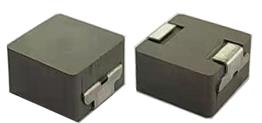
Specifications
Datasheet facts
- Recommended land pattern
- Two 5 × 3.25 mm pads, 8 mm apart, 14.5 mm overall
- Inductance test condition
- 1 MHz, 1.0 V, 25 °C
- Current definitions
- Isat: inductance drops about 30%; Idc: temperature rise about 40 °C
- Soldering
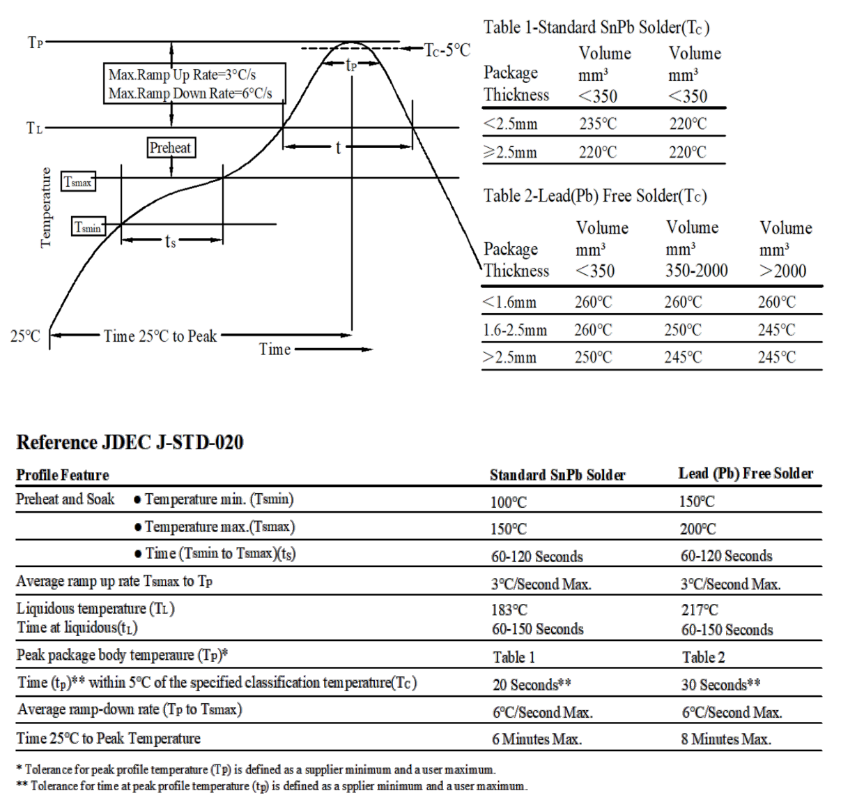
- Reflow per J-STD-020
- Operating temperature (ambient + self-heating)
- -55 ~ +125 °C
- Storage temperature
- -55 ~ +125 °C
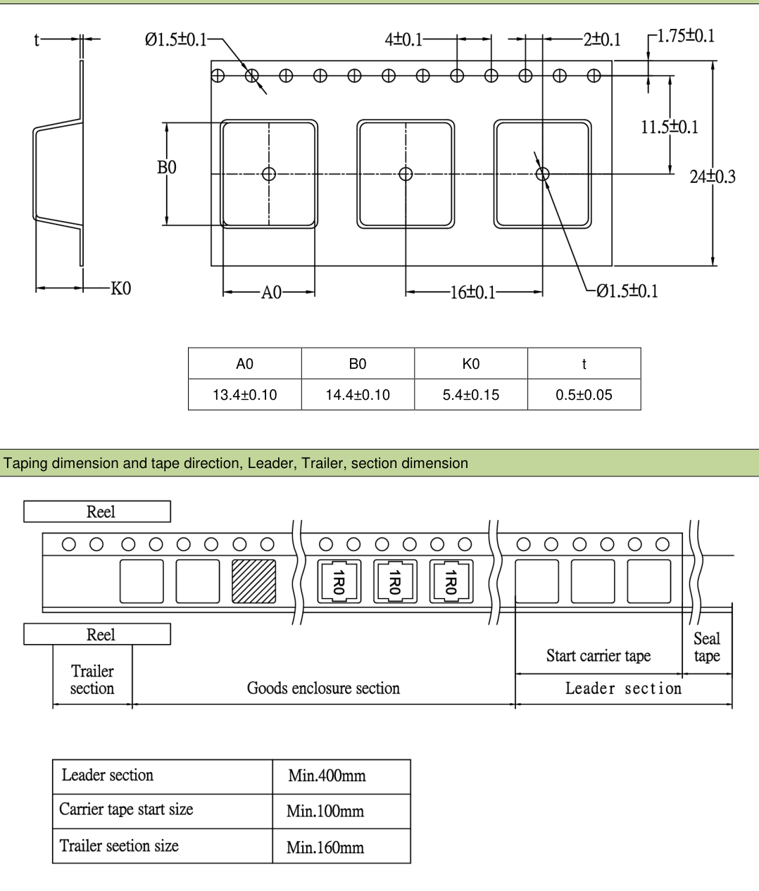
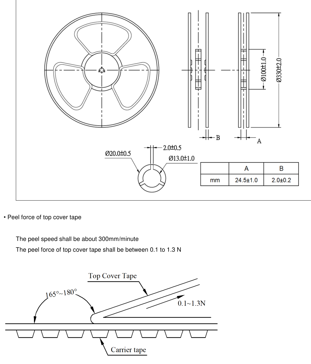
- Packaging
- 500 pieces per reel; tape pocket 13.4±0.10 × 14.4±0.10 × 5.4±0.15 mm
Datasheet VCMA-1350-XXX-M-1A, revision A4, 2025-11-26, page 4
Characteristic curves
Typical curves from the MAZO datasheet, for reference only.
Soldering and packaging
Alternative to these parts
VCMA-1350-6R8-M-1A matches the parts below in footprint class and nominal value. Check the pads and test samples before switching.
| Brand | Part number | L | Isat | Irms | DCR max | Size | Footprint | Recommended pads | VCMA-1350-6R8-M-1A vs. this part |
|---|---|---|---|---|---|---|---|---|---|
| Cyntec | CMLB135T-6R8MSCMLB135T | 6.8 µH | 15 A · 30% | 11.5 A · 40 °C | 15 mΩ | 13.45 × 12.6 × 4.8 mm | Pad-compatible | 5 × 3.25 mm, gap 8 mmSame as MAZO | Drop-in candidate |
| Bourns | SRP1245A-6R8MSRP1245A | 6.8 µH | 21 A · 20% | 11 A · 40 °C | 18.5 mΩ | 13.5 × 12.5 × 4.8 mm | Pad-compatible | 5 × 3.1 mm, gap 8 mmClose to MAZO (0.3 mm off) | With design margin |
| Cyntec | CMLS135T-6R8MSCMLS135T | 6.8 µH | 23 A · 30% | 11 A · 40 °C | 18.5 mΩ | 13.45 × 12.6 × 4.8 mm | Pad-compatible | 5 × 3.25 mm, gap 8 mmSame as MAZO | Weaker figures |
| Vishay | IHLP5050EZEK6R8M01IHLP-5050EZ-01 | 6.8 µH | 21 A · 20% | 11 A · 40 °C | 18.5 mΩ | 13.2 × 12.9 × 5 mm | Same footprint class | 4.953 × 3.226 mm, gap 8.28 mmClose to MAZO (0.28 mm off) | With margin; check the pads |
| Vishay | IHLP5050EZEK6R8MA1IHLP-5050EZ-A1 | 6.8 µH | 21 A · 20% | 11 A · 40 °C | 18.5 mΩ | 13.2 × 12.9 × 5 mm | Same footprint class | 4.953 × 3.226 mm, gap 8.28 mmClose to MAZO (0.28 mm off) | With margin; check the pads |
What each comparison means (5)
- Cyntec CMLB135T-6R8MS: Same inductance, 6.8 µH vs MAZO 6.8 µH. Saturation current 15 A (30% drop) vs MAZO 16.5 A typ. (30% drop); heating current 11.5 A (40 °C rise) vs MAZO 11.5 A typ. (40 °C rise). DCR 15 mΩ max vs MAZO 13.5 mΩ max. Body 13.45 × 12.6 × 4.8 mm vs MAZO 13.8 × 12.9 × 5 mm, MAZO 0.2 mm taller. Same land pattern as MAZO (two 5 × 3.25 mm pads 8 mm apart). Verdict: drop-in candidate (MAZO Isat not lower, Idc not lower at 40 °C rise, DCR lower, less conduction loss). Before switching, verify brands define Isat/Irms differently: check the real peak current and allowed temperature rise, height clearance and test samples.
- Bourns SRP1245A-6R8M: Same inductance, 6.8 µH vs MAZO 6.8 µH. Saturation current 21 A (20% drop) vs MAZO 16.5 A typ. (30% drop), rated on different bases so not directly comparable; heating current 11 A (40 °C rise) vs MAZO 11.5 A typ. (40 °C rise). DCR 18.5 mΩ max vs MAZO 13.5 mΩ max. Body 13.5 × 12.5 × 4.8 mm vs MAZO 13.8 × 12.9 × 5 mm, MAZO 0.2 mm taller. Land pattern close to MAZO's: two 5 × 3.1 mm pads 8 mm apart vs MAZO two 5 × 3.25 mm pads 8 mm apart (overall span differs by 0.3 mm). Verdict: replaceable with design margin (Idc not lower at 40 °C rise, DCR lower, less conduction loss). Before switching, verify brands define Isat/Irms differently: check the real peak current and allowed temperature rise, height clearance, the land pattern against both drawings and test samples. Both parts are AEC-Q200.
- Cyntec CMLS135T-6R8MS: Same inductance, 6.8 µH vs MAZO 6.8 µH. Saturation current 23 A (30% drop) vs MAZO 16.5 A typ. (30% drop); heating current 11 A (40 °C rise) vs MAZO 11.5 A typ. (40 °C rise). DCR 18.5 mΩ max vs MAZO 13.5 mΩ max. Body 13.45 × 12.6 × 4.8 mm vs MAZO 13.8 × 12.9 × 5 mm, MAZO 0.2 mm taller. Same land pattern as MAZO (two 5 × 3.25 mm pads 8 mm apart). Verdict: MAZO figures are weaker, consider only with ample margin (MAZO Isat about 28% lower, Idc not lower at 40 °C rise, DCR lower, less conduction loss). Before switching, verify brands define Isat/Irms differently: check the real peak current and allowed temperature rise, height clearance and test samples.
- Vishay IHLP5050EZEK6R8M01 (IHLP-5050EZ-01): Same inductance, 6.8 µH vs MAZO 6.8 µH. Saturation current 21 A (20% drop) vs MAZO 16.5 A typ. (30% drop), rated on different bases so not directly comparable; heating current 11 A (40 °C rise) vs MAZO 11.5 A typ. (40 °C rise). DCR 18.5 mΩ max vs MAZO 13.5 mΩ max. Body 13.2 × 12.9 × 5 mm vs MAZO 13.8 × 12.9 × 5 mm. Land pattern close to MAZO's: two 4.953 × 3.226 mm pads 8.28 mm apart vs MAZO two 5 × 3.25 mm pads 8 mm apart (gap differs by 0.28 mm). Verdict: replaceable with design margin, pads need checking (Idc not lower at 40 °C rise, DCR lower, less conduction loss). Before switching, verify brands define Isat/Irms differently: check the real peak current and allowed temperature rise, the land pattern against both drawings and test samples.
- Vishay IHLP5050EZEK6R8MA1 (IHLP-5050EZ-A1): Same inductance, 6.8 µH vs MAZO 6.8 µH. Saturation current 21 A (20% drop) vs MAZO 16.5 A typ. (30% drop), rated on different bases so not directly comparable; heating current 11 A (40 °C rise) vs MAZO 11.5 A typ. (40 °C rise). DCR 18.5 mΩ max vs MAZO 13.5 mΩ max. Body 13.2 × 12.9 × 5 mm vs MAZO 13.8 × 12.9 × 5 mm. Land pattern close to MAZO's: two 4.953 × 3.226 mm pads 8.28 mm apart vs MAZO two 5 × 3.25 mm pads 8 mm apart (gap differs by 0.28 mm). Verdict: replaceable with design margin, pads need checking (Idc not lower at 40 °C rise, DCR lower, less conduction loss). Before switching, verify brands define Isat/Irms differently: check the real peak current and allowed temperature rise, the land pattern against both drawings and test samples. Both parts are AEC-Q200.
How the figures are compared
Isat and Irms follow each datasheet's own definition, shown after the figure. MAZO figures are typical values from its spec table.
Recommended pads: pad width × pad length, then the gap between the two pads, from each datasheet, compared with MAZO's.
Same footprint, other values
Same 13.8 × 12.9 mm body, by inductance. Check the height before swapping.
| Part number | L | Isat | Idc | DCR max | Height | Unit price |
|---|---|---|---|---|---|---|
| VCMA-1350-1R5-M-1A | 1.5 µH | 39 A | 23 A | 3.1 mΩ | 5 mm | $0.75 |
| VCMA-1350-2R2-M-1A | 2.2 µH | 28 A | 21 A | 4.6 mΩ | 5 mm | $0.72 |
| VCMA-1365-2R2-M-1A | 2.2 µH | 35 A | 30 A | 3.2 mΩ | 6.5 mm | $0.79 |
| VCMA-1350-3R3-M-1A | 3.3 µH | 24 A | 16 A | 6.9 mΩ | 5 mm | $0.75 |
| VCMA-1365-3R3-M-1A | 3.3 µH | 25 A | 22 A | 4.5 mΩ | 6.5 mm | $0.79 |
| VCMA-1350-4R7-M-1A | 4.7 µH | 20.5 A | 14 A | 9.2 mΩ | 5 mm | $0.75 |
| VCMA-1365-4R7-M-1A | 4.7 µH | 24 A | 20 A | 6.9 mΩ | 6.5 mm | $0.79 |
| VCMA-1350-5R6-M-1A | 5.6 µH | 20 A | 12 A | 12 mΩ | 5 mm | $0.75 |
| VCMA-1365-5R6-M-1A | 5.6 µH | 22 A | 18 A | 8.2 mΩ | 6.5 mm | $0.90 |
| VCMA-1365-6R8-M-1A | 6.8 µH | 20 A | 16 A | 11 mΩ | 6.5 mm | $0.93 |
| VCMA-1350-100-M-1A | 10 µH | 14 A | 8.5 A | 21.5 mΩ | 5 mm | $0.75 |
| VCMA-1365-100-M-1A | 10 µH | 18 A | 15 A | 17 mΩ | 6.5 mm | $0.93 |
Same value, other sizes
Smallest first. A larger body usually carries more current; the pads differ.
| Part number | L | Isat | Idc | DCR max | Body | Unit price |
|---|---|---|---|---|---|---|
| VCMA-0420-6R8-M-1A | 6.8 µH | 2.6 A | 2 A | 185 mΩ | 4.75 × 4.45 × 2 mm | $0.36 |
| VCMA-0530-6R8-M-1A | 6.8 µH | 4 A | 3 A | 90 mΩ | 5.7 × 5.4 × 3 mm | $0.33 |
| VCMA-0630-6R8-M-1A | 6.8 µH | 6 A | 5 A | 48 mΩ | 7.3 × 6.8 × 3 mm | $0.30 |
| VCMA-1040-6R8-M-1A | 6.8 µH | 12.5 A | 8 A | 25 mΩ | 11.5 × 10.3 × 4 mm | $0.55 |
Buy
| Quantity | Unit price | Extended |
|---|---|---|
| 5–49 | $0.75 | $3.75 |
| 50–149 | $0.54 | $27.00 |
| 150–499 | $0.436 | $65.40 |
| 500–2999 | $0.338 | $169.00 |
- Minimum order
- 5 pieces
- Order multiple
- 1 piece
- Availability
- Factory stock
- Dispatch preparation
- 2 days
Dispatch preparation and shipping transit are separate. Arrival is estimated; the confirmed route and shipment tracking determine delivery.
- Standard full-reel quantity
- 500 pieces
- Packed as
- Cut tape · 5 pieces
- Cut-tape fee
- None
- Online order limit
- 2999 pieces
Packaging and handling charges are shown in the cart. Shipping, duties and tax are confirmed separately.
Add this quantity to your cart to review order charges and the available payment steps. Sign in if prompted.
Selection and use
How to select
Choosing inductance
L ≈ (Vin − Vout) × Vout ÷ (Vin × fsw × ΔI), with ΔI at 20–40% of the output current. The series covers 0.22–33 µH in one body, so changing the value needs no new layout.
Saturation current Isat
the current at which inductance falls about 30%; keep the peak current below it.
Heating current Idc
the current that raises the part about 40 °C above a 25 °C ambient; ambient plus rise stays within 125 °C.
DC resistance
sets the conduction loss. Typical 0.54–50 mΩ across the series; use the maximum for loss budgets.
Rated voltage
75 V maximum; check it against the input voltage.
Height
Max 5.0 mm. VCMA-1365 shares the land pattern at 6.5 mm with more inductance; smaller: VCMA-1040.
Industry and product applications
VCMA-1350-6R8-M-1A is a VCMA-1350 series part for evaluation in automotive electronics.
Manufacturer-listed series applications
Automotive applications.
MAZO datasheet: VCMA-1350-XXX-M-1A, revision A4, 2025-11-26 — applications on page 1
Circuit applications to evaluate
These are series applications and engineering evaluation examples. Select VCMA-1350-6R8-M-1A against the required inductance, peak and RMS current, switching frequency, temperature rise and PCB footprint. Inclusion here does not establish suitability for a particular design or qualification of the finished product.